The Electric Giraffe Project

The electric giraffe (aka 'Rave Raffe') is a shy, nocturnal creature of the Playa. It can sometimes be found roaming the streets of suburbia where it elicits awe amongst the spectators. Native of Southern California, the 'Raffe can sometimes be coaxed further afield for special occasions.

Enter now the world of the Electric Giraffe, and behold the beauty of its design, marvel at its engineering and revel in the presence of the World's first robotic giraffe.

6th May, 2015 by

The error message “Unable to create the display plug-in MPForum.Forum.1” has been plaguing me on my laptop. Whenever I launch the MPLAB 8.92 programming environment it immediately crashes. I spent hours last year trying to fix it to no avail, and I spent almost all of yesterday too. The Microchip forums have a number of posts on the subject but none of them offered a solution for me.

Finally, I have found a solution! The problem is caused by DEP (Data Execution Prevention). The MPForum.dll has a bug that triggers DEP into terminating the process. To work around this, simply disable DEP for mplab.exe. This is done in the System control panel, search Google for exact details.

25th April, 2015 by

Well, hello everyone!  It’s been far too long since I (Lindsay) posted here on our website.  But, as you may have heard, things got pretty hectic in 2014 after the Maker Faire in San Mateo.  When I got home, there was an email from the White House, and long story, a VERY long story short, we ended up on the White House Lawn with the President of the United States petting our Electric Giraffe.

And I say “our” because this project is drawing in lots of people around it.  From one time helpers to people consistently being around to help work on him, I find myself saying “our project” and “we are working on” quite a lot.  And so I want to thank everyone who’s ever turned a bolt, welded a piece, soldered a connection, or wrote code and designs for this machine, for getting “us” to the White House lawn, something I could have never imagined when I started this project in late 2004.

To Louise, Sherry and Dale and everyone else at Maker Media and my good friend Alan Murphy of Murphy Surplus in San Diego, I thank you so very much!  That Giraffe would never have made it without your huge efforts to get him across the country on such short notice.

But most of all, I want to thank my friend and programmer, Russell Pinnington.  As of this writing, I fully acknowledge his part ownership of this project, from the massive efforts he’s made in both writing the code for his operation, and in taking his own personal time to fly out here once a year to be here for the Maker Faire in San Mateo.  Without Russell, we would not have “Russell” the giraffe, speaking to everyone who pets him, including, most surprisingly of all, President Barack Obama, in his own back yard.  Russell has been amazing in his abilities and I cannot ever thank him enough for what he’s put into this project, one that is still on its way to becoming even more of a “Techno-beast” than we ever imagined.  Yes, the “Rave-Raffe” has come a _long_ way indeed.

In the meantime, please feel free to search out the net for items related to “Obama Giraffe”.  From Google Images to Youtube, you’ll find some pretty humorous stuff including the giraffe being dissed by a well known political dissident with his own talk show.  When I saw that, I simply smiled, and one good friend of mine summed it up perfectly.  “You sir, have arrived!”

Yes, we did.

electric_giraffe_burningman_obama_lead

Russell, and Russell, and I, on the White House grounds, June 18th, 2014.

20th April, 2015 by

DipTrace is a good schematic/PCB editor, but the jagged graphics leave a lot to be desired. You can make it a bit easier on your eyes by using your graphics card driver’s control panel to force anti-aliasing on. The image becomes a little blurry, but overall I find it easier to read.

For an nVidia card open the NVIDIA Control Panel from your start menu and select “Manage 3D Settings”. Choose the “Program Settings” tab then press “Add” and locate the DipTrace executable (default: c:\program files\diptrace\schematic.exe). In the list below set “Antialiasing Mode” to “Override any application setting” and “Antialiasing Setting” to “8x”. If DipTrace is already running you may need to restart it for it to take effect. DipTrade must be using either OpenGL or Direct3D for rendering.
AMD cards have similar settings.

Click on the image below to see difference. When the image is displayed you may need to click again to view it at its full size.

diptrace-graphics

19th April, 2015 by

Hard Disk

Disasters are rarely caused by a single failure. Instead, the fates conspire to align a series of small misfortunes which combine together to create a catastrophe. Such an event befell the Raffe recently.

The tale begins almost exactly one year ago. In May 2014 I made my way, laptop in hand, to San Diego in order put the finishing touches on the Raffe’s software ready for the Bay Area Maker Faire. At home I do all the development work on my PC, but for travel I switched to my laptop. This was the first misfortune – the PIC microchip programming software MPLAB refused to run on my laptop. I spent a few hours trying fruitlessly to persuade it to run before deciding to cut my losses and switch to Lindz’s laptop. Even though our laptops are identical makes and models running the same operating system, MPLAB runs on his laptop but not mine.

I spent my two weeks of vacation working hard to polish up the new software – all new LEDs necessitated some hardware modifications to the custom electronics and lots of firmware modifications, plus updates to the PC software. All of this was done on Lindz’s laptop. Usually I commit my software modifications to SVN, a change management system that keeps track of the changes that have been made as well as making sure there is another copy of the files, but because I was in San Diego I could not connect to the network, so the changes were not committed. This was misfortune number two.

With the changes complete we went to the Maker Faire and everything worked splendidly. The new spots and LEDs were much brighter and looked great. When the faire finished there was no time to relax, I left immediately for the long flight home. This was the third misfortune: I did not have time to take a copy of the software. We both have an extremely busy schedule, and after the faire ended we quickly forget that I did not have the latest copy of the software.

Fast forward almost a year, when misfortune number four struck: Lindz’s cat pushed his laptop off a table, destroying its hard drive. I sent him a copy of the software to load onto a spare machine and it was only then that we realised that what I’ve sent him is out of date. Misfortune five, the laptop had no backup schedule. Two weeks of full-time work were now stuck on a broken hard drive. Recovery was estimated at $1,250 which was far too much to afford.

The only option that remained was to redo the work. It was not a nice prospect, because I already knew just how difficult it was. There was little choice however, so I spent almost the next two weeks programming 16 hours a day to recreate the work that had been lost. That work is now complete, so not only has the lost work been redone, but new features have been added that will make it better than ever this year.

24th May, 2014 by

After months of preparations and changes/mods/additions to the Electric Giraffe, we’re here at Maker Fair! Russell himself has flown out from the UK and we had a great time rebuilding all new LED driven spots for the Giraffe! I would like to thank Phillip Burgess for his support/advice in setting up the Neopixel LED network. I would also like to thank Maker Place in San Diego for their complimentary laser cutting work on the giraffe’s hexagon spots. We’re going to look better than ever in the dark room as a result!  Here is mister raffe himself in my driveway, on his first new LED spot test.   The colors and sheer brightness were beyond what we expected, and we cannot wait to show him off at the faire!

Pre-show-raffe


16th April, 2014 by

IMG_0255

I just spent at least twelve solid hours of work debugging some firmware, finally solving the issue by flipping a single bit from a zero to a one. Such is the life of a computer programmer.

30th March, 2014 by

The Electric Giraffe Project now has an all-new website!

Ok, it looks almost exactly like the old one, but it’s been rewritten from the ground up using a different CMS and using responsive design techniques, meaning it will now work much better on mobile and tablet devices.

Rather than using a traditional fixed width design, a responsive design allows the size of the page to adjust to the size of the viewing area, be that the size of the browser window on a PC or the size of the screen on a mobile device. Further to that, the use of CSS @media queries allows the layout of the website to change dynamically based on the size of the page. One example of this is that the website’s main menu appears on the left on a wide screen, but is moved to the top on a narrow screen to allow more room for the articles.

23rd March, 2014 by

Hello everyone!

I’ve been a little silent here, mostly because I post to my page on facebook. You can find me there as “Electric Giraffe” on an artist page.

SO…what have I been up to? Well, 2014 started off with a bang in xmass 2013, with me showing up at a huge candy cane lane out where I live, wearing all my xmass lights and reindeer antlers! That was such a fun gig, watching the kids completely lose it when they saw a 1 ton reindeer walk into their neighborhood!

And just prior to that, I appeared at the first ever San Diego Maker Faire! It was at the Del Mar Fair Grounds and I so hope this event will transform into a full blown Maker Faire for the San Diego area! We deserve it! The organization can be found at http://sandiegominimakerfaire.org/ Please check them out and get involved!

Since then I’ve appeared in several locations recently:

Maker Place, with Brian Salmon having me show up and play music for their open house events. Maker Place is where Lindsay is making me new hexagon Giraffe Spots with their laser cutter.

Washington Middle School where I hung out with their robotics class for an evening.

The Aerospace Museum in Balboa Park! Imagine, me, the Robot Giraffe, in Lindsay’s personal place of worship! After all the years he’s spent in there as a kid, to have me, something he built, featured inside the very same museum! That was a fun day, that will likely lead to something more with the City of San Diego. News to come!

Fox 5 news: I did their morning news show! Take a look here for a fun news segment! http://fox5sandiego.com/2014/03/17/made-in-san-diego/#axzz2wpXAu0je

Plus other appearances at more schools to support their robotics programs.

Maker Faire is also talking about sending me to New York and possibly London! Please wish me luck in getting there!

30th June, 2013 by

I've been designing a very simple new circuit to control the servos in the forthcoming new neck.

Each joint calls for a two channel servo driver, and I decided to add current sensing capability to this.  By continuously monitoring the current drawn by the motor, the circuit should be able detect the increase in current that occurs when the motor is stalled – because the neck has hit an obstruction or the mechanism has jammed – and shut down the servo drive before too much damage is done.

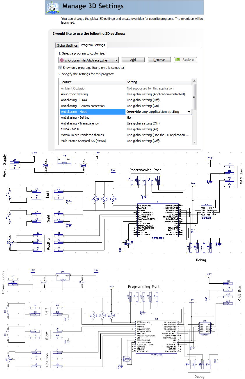
The circuit is split into three parts: Firstly, a current sensing resistor; second, a low-pass filter; thirdly, an amplifier.  The output from this is then fed into a standard CAN (Controller Area Network) circuit driven by a PIC chip.

The principle of measuring current with a current sense resistor is very simple: you put a low-value resistor in series with the power supply, and measure the voltage across it.  The resistor can be placed either at the power supply's positive terminal ("high-side"), or negative terminal ("low-side").  Using the low side is slightly simpler as one end of the resistor is grounded.  It has some disadvantages (the ground voltage level for the circuit being sensed is raised up by the voltage across the resistor, and it cannot measure if the load is shorted to ground), however those aren't a problem for this application.

The current flowing through the motor passes through the current sense resistor, developing a small voltage of V = IR.  I have estimated the maximum servo current to be 5A (this will be confirmed when I get the actual servo specifications).  With a resistance of 0.05 ohms, this will give a voltage range of 0 – 0.25V for a current of 0 – 5A.

The power rating of the resistor is important here.  Power is calculated as P = I2R, so at 5A this would give me a power rating of 5*5*0.05 = 1.25W.  This is the minimum wattage for the current sense resistor.

Before being amplified, the signal passes through a 7Hz low-pass RC filter.  This is simply a 220 ohm resistor and a 100uF capacitor arranged so as to block any high frequency noise that may be present on the sensor, for example voltage spikes caused by the servo motor's operation.  The motor will only need to be sampled a few times per second, so I chose 7Hz as the cut-off frequency for the filter to avoid any aliasing effects when sampling.  Aliasing occurs when signals are sampled more slowly than half their maximum frequency component, and causes the high frequencies to appear as if they were low frequency changes, giving you an erroneous result.

The next stage is a non-inverting amplifier.  An amplifier is necessary here because the chip's analogue to digital converter is not especially precise, so amplifying the signal from 0 – 0.25V into the range 0 – 2.5V allows me to use more of its range, giving a more precise current measurement.

Because the amplifier output needs to operate down to zero volts, I chose the LM358 dual operational amplifier.  This 8-pin IC contains two amplifiers with an output swing of 0V to Vcc -1.5V.  Normal amplifiers cannot drive their output to the power rails, so a "rail to rail" amplifier is needed for an application like this – however in this instance I only need to include the 0V rail, so the LM358 will do the job just fine.

The two feedback resistors are arranged to give me an amplifier gain of 10.

Finally, the signal passes through a 20 ohm resistor before being fed into the PIC chip's analogue to digital converter.  The 20 ohm resistor is recommended to ensure the amplifier remains stable when driving a capacitive load.

10th January, 2013 by

This is what happens if you forget to restore your transformation matrix after doing a rotation in OpenGL – oops!